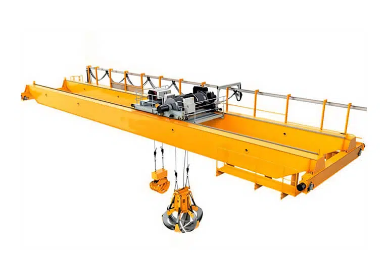
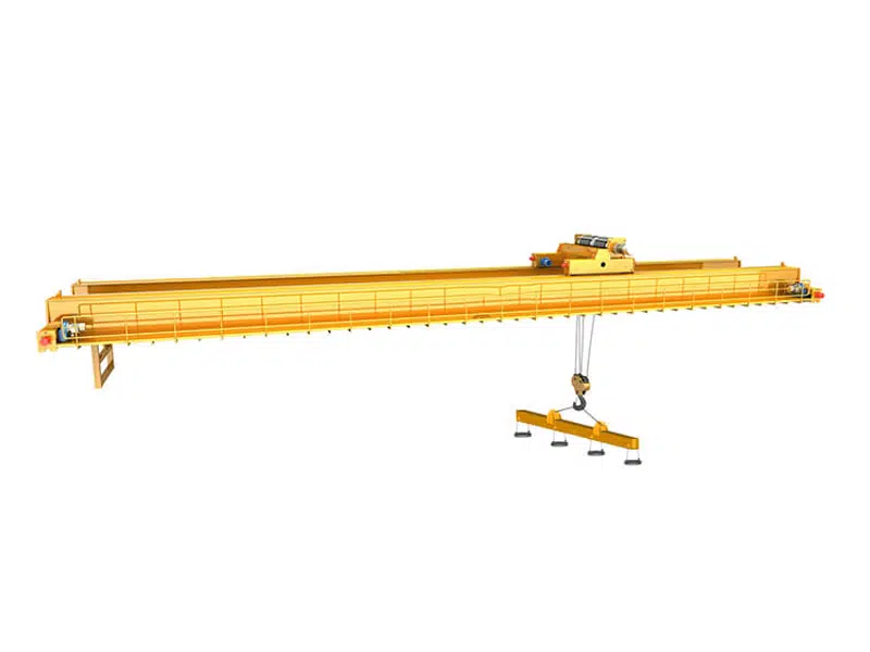
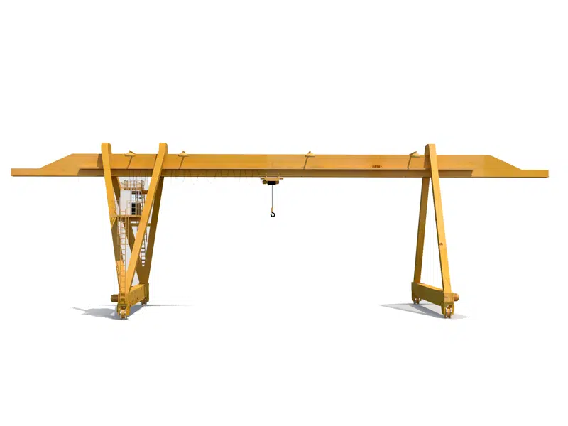
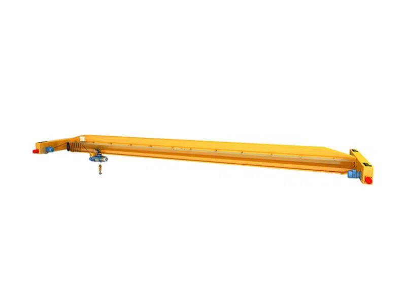
Double Trolley Overhead Cranes are used to lift long and big loads with the capacity of (2.5+2.5) to (200+200) tons.

| Type | QE |
| Lifting Capacity | (2.5+2.5) to (200+200) tons |
| Lifting Height | Custom Height |
| Span | 6 to 35 m |
| Lifting speed | 3-11.5m/min |
| Trolley running speed | 5-40.1m/min |
| Crane running speed | 40-71m/min |
| Working Duty | A4,A5,A6,A7 |
Introduction
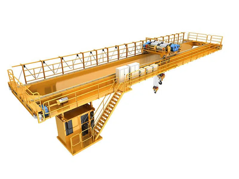
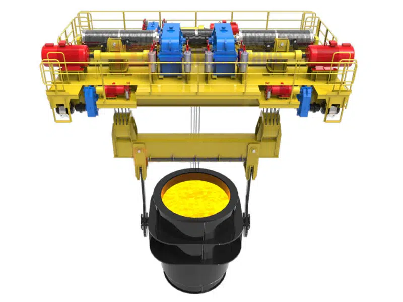
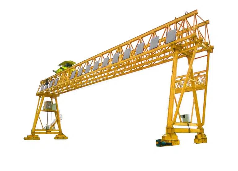
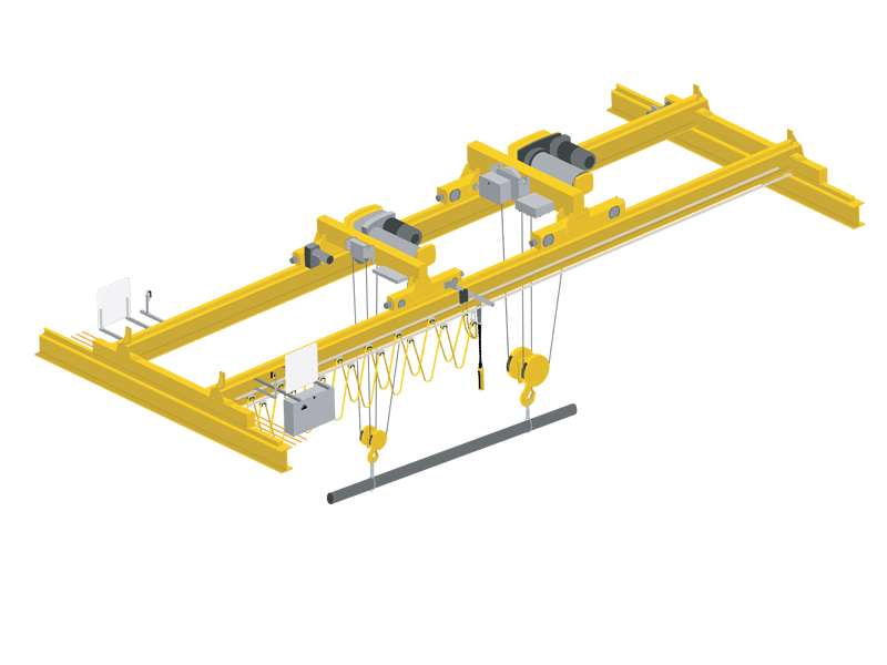
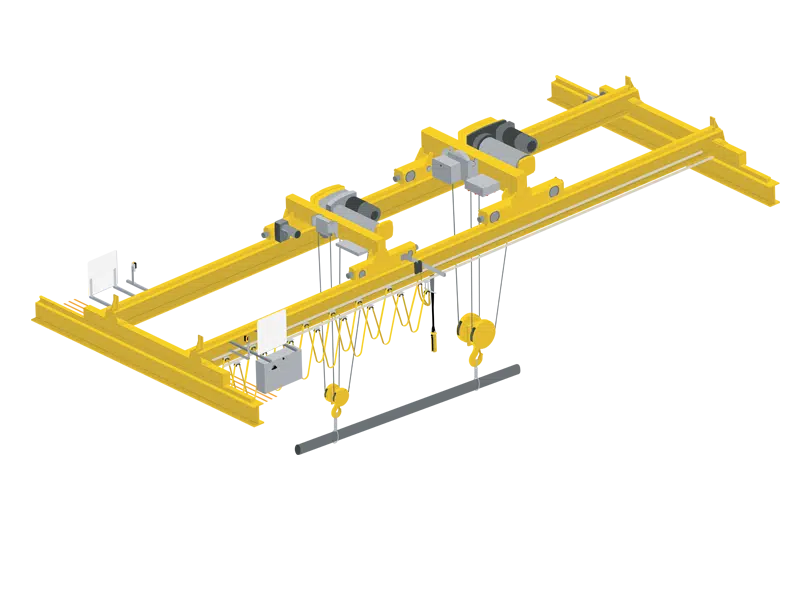
QE type double trolley double girder bridge crane uses the structure of double girder, double track, and double trolley;
Each lifting trolley of the QE type double trolley double beam bridge crane is equipped with an independent transmission system. The two lifting trolleys have their own lifting mechanisms, which can not only complete the lifting independently but also complete the work in coordination.
In addition, it is equipped with lifting lugs, lifting holes, etc. on the main components, which can realize convenient transportation and loading and unloading.
What can we offer you?
We can provide you with the main Double Trolley Double Girder Overhead Crane
Lifting weight 5ton, 10ton, 16 ton, 20 ton, 25 ton, 32 ton, 50 ton, 75 ton, 100ton, 125 ton, 160 ton, 200ton, 250 ton, 300 ton, 400 ton,
Span 10.5m-31.5m;
Lifting height 3m-30m;
Work level (A3, A4);
If we can’t satisfy you, we can customize it for you.
Features
Efficient and stable working performance;
Reliable quality and high-cost performance;
Compact structure, lightweight;
Easy to store or transport;
Easy to install and maintain;
WeiHuaCrane Advantages
Application Scenarios
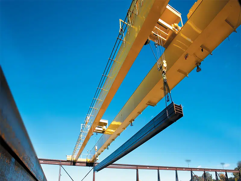
Mainly used for transporting long objects, double hooks can maintain balance, and operate independently, and can also adjust the angle of materials.
Main Structure and Feature
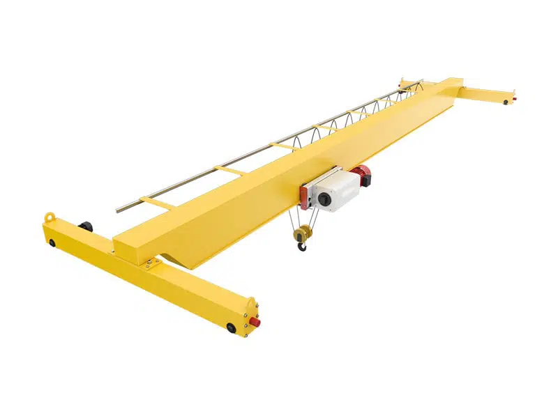
Mainly consists of bridge, trolley, crane traveling mechanism, and electrical system, etc.
Bridge Frame
Consists of the main girder, end beam, walkway, railing, overhaul crane cage, cab, and its platform, etc.
Main Girder
Double main girder, welded box girder, and camber meet the national standard
Steel material is Q235B or Q345B (similar to foreign steel type Fe37 or Fe52).
The main weld adopts Lincoln welding and nondestructive test.
End Girder
The main end beam is a rigid contaction. The middle of the two-end beam is detachably contacted by bolts.
The whole bridge is separated into two pieces for transportation and installation.
Others
Lay the track on the upper cover plate for trolley traveling.
Install the crane traveling mechanism on the side of the walkway which contacts with the main girder.
Install the trolley sliding wire on the other side.
There is a railing on the outboard of the walkway in order to ensure the operator’s safety during maintenance.
The cab usually hangs beneath the bridge with electrical control equipment in it and mainly for operator use.
Trolley
Consists of a trolley frame, lifting mechanism, and trolley traveling mechanism, etc.
Trolley Frame
Welded of steel plate with high intensity and strong rigidity.
Equipped with lifting mechanism and trolley traveling mechanism.
Lifting Mechanism
One set of independent driving devices for single hook and two separate driving devices for double hook (main and auxiliary).
Lifting mechanism working principle, through high speed rotating of YZR type crane special motor, and gear coupling drive involute gear reducer. Then the low-speed shaft of the reducer turns the wire rope drum. As long as the control of motors and their positive and negative rotation can achieve the lifting function of the hook.
In order to ensure the security and reliability of the lifting mechanism, the brake is installed on the high-speed shaft of the reducer. And the load limiter is installed on the bearing pedestal which supports the drum to avoid overload. The mechanical drawing is as follows:

- Main overload limitation;
- Main lifting motor;
- Main lifting gear coupling;
- Main lifting drum;
- Main lifting brake wheel coupling;
- Main lifting brake;
- Main lifting reducer.
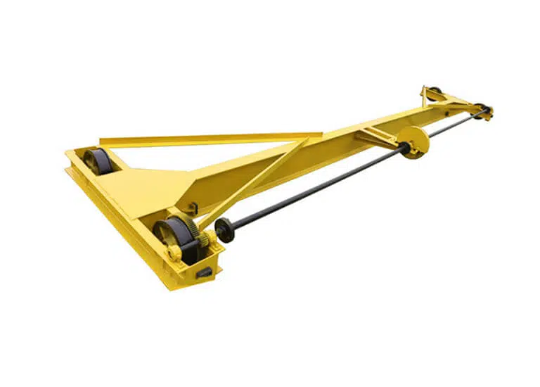
Trolley Traveling Mechanism
Trolley traveling mechanism working principle, the involute vertical gear reducer driven by a motor. The low-speed shaft of the reducer contacts to the active wheel of the trolley frame in the way of centralized driving. The motor adopts double-output gear and there is a brake on one end of it.
There are four wheels installed under the trolley. Two of them are active wheels and the others are driven wheels. Driving devices include

1. Motor; 2. Brake; 3. Reducer; 4. Compensating shaft; 5. Coupling; 6. Wheels, etc.
Crane Traveling Mechanism
There are four traveling wheels installed on each side of the two end beams. Two of them are active wheels and the others are driven ones. The driving device of active wheels is installed on the walkway. Here adopt two sets of symmetrical independent driving devices and we call them respectively driven.
The reducer adopts circular-arc gear one of which load capacity is higher than the involute gear reducer of the same type. All of the mechanisms adopt rolling bearing with A.C. electromagnetic block brake.
Driving devices include 1. Reducer; 2. Motor; 3. Brake; 4. Coupling; 5. Coupling; 6. Wheels, etc are shown in the mechanical drawing as follows:

The contaction of the mechanical parts all adopts gear coupling. In this way, it can work well by gear coupling compensated even there is an error caused in manufacture and installation or deflection between the parts caused by bridge deformation when loading.
Active and driven wheel axle support on the angular bearing box for easy assembly and maintenance.
Other Equipment
Bumper
The crane bumpers are installed on both ends of the two end beams. The trolley bumpers are installed under the trolley frame, and usually polyurethane buffer. Also can choose according to customer’s requirement. Use to reduce the collision possibility between two cranes within the same span or the impact influence caused when the trolley reaches the limit position at both ends.
Crane Conductor Wire Frame
In order to prevent the hook or wire rope collide with high voltage supply when trolley run at the limiting position, the crane conductor wireframe is installed on the end close to a power supply under the two main girder of the bridge.
Crane Pantograph
The pantograph is installed on the bottom of the main girder. The power line is installed in the three sets of current collectors to supply the power of the whole crane.
Electrical System
The electric control box layout is reasonable, easy to repair
Security trolley line or angle steel trolley line
External cables are equipped with mark line number
Trolley moving’ power is supplied by a flat cable
The conductor is I steel or C shape sliding line
Safety sliding touchline with high conductive rate and low-pressure drop; current collector with high speed.
Lifting and crane can be independently controlled; also can work separately or together.
Limit and Safety Switch
Crane traveling, trolley traveling, and lifting mechanisms are all equipped with limit switches to limit the travel distance of every mechanism.
The circuit will be cut off when the limit switch works, then the machine shuts down. It will move in the opposite direction when switches on the power again. Thus, ensure safety.
n order to prevent the operators and maintenance staff from the accident, the safety switch is installed on the access door of the walkway which leads the way from cab to bridge, and also on the railing which leads to the end beam.
Operation Mode
Cab control and ground control
Special cabin for bridge crane or capsule driver room, open vision, comfortable operation.
The cable has an open style, close style, can fix on left or right
The cab hangs under the side walkway of the crane bridge close to the end beam. Inside of it includes control equipment of each mechanism, distribution board, emergency switch, and bell push button, etc.
Ground control (wired or remote), without a professional driver
Choose according to customer’s different requirements
Optional Functions
Speed governing of each operating mechanism (1:10 or more)
Overload limiter, alarm display, load weighing, and display
Height limiter
Hook spur changes of main and auxiliary hook for single trolley
Central lubrication
PLC control, fault detection, display records, and print system
Double Trolley Double Girder Overhead Crane Parameters Table
| Lifting capacity | Span | Lifting height | Lifting speed | Trolley speed | Crane speed | Work duty | Track type |
| S(m) | m | m/min | m/min | m/min | |||
| 5 ton | 10.5~31.5 | 6~16 | 11.5 | 37.2 | 70.6 | A3~A7 | P38 |
| 10 ton | 10.5~31.5 | 6~16 | 8.5 | 37.4 | 70.6 | A3~A7 | P38 P43 |
| 16 ton | 10.5~31.5 | 6~16 | 7.9 | 40.1 | 74.3 | A3~A7 | P43 |
| 20 ton | 10.5~31.5 | 6~16 | 7.2 | 40 | 75.1 | A3~A7 | P43 |
| 32 ton | 10.5~31.5 | 6~18 | 6 | 37 | 64.9 | A3~A7 | QU70 |
| 50 ton | 10.5~31.5 | 6~16 | 6 | 31.3 | 58.5 | A3~A7 | QU80 |
| 75 ton | 10.5~31.5 | 6~20 | 3.9 | 31.3 | 61 | A3~A7 | QU100 |
| 100 ton | 13~31 | 6~20 | 3.1 | 33.6 | 61.8 | A3~A7 | QU100 |
| 125 ton | 13~31 | 6~20 | 3.9 | 33 | 62.3 | A3~A7 | QU100 |
| 160 ton | 13~31 | 6~22 | 3.5 | 40 | 68 | A3~A7 | QU120 |
| 200 ton | 13~31 | 6~20 | 2.6 | 32 | 48 | A3~A7 | QU120 |
| 250 ton | 13~31 | 6~20 | 2.2 | 32 | 50 | A3~A7 | QU120 |
| 300 ton | 13~31 | 6~24 | 2.4 | 28 | 42 | A3~A7 | QU120 |
| 350 ton | 13~31 | 6~24 | 2.2 | 28 | 42 | A3~A7 | QU120 |
| 400 ton | 13~31 | 6~24 | 2.6 | 31 | 45 | A3~A7 | QU120 |
| 450 ton | 13~31 | 6~24 | 2.1 | 27 | 42 | A3~A7 | QU120 |
Drop Us Message
After receiving your message, our engineers will first customize the Double Trolley Overhead Crane and make design drawings for you according to your needs, and then the sales manager will provide you with the price and contact you. Please wait.
In order to customize the design drawings and the latest price for you as soon as possible, please fill in as much useful information as possible in the Message.
Of course, you can also send this information to our email: [email protected].